Search Your Paper

Thursday, January 29, 2015

punjabtechnicaluniversity.blogspot.in


There many techniques available for estimating a project:-

 Function points

 Use Case points

 WBS etc etc.

punjabtechnicaluniversity.blogspot.in


PMP document forms the bible of a project.It has normally these sections :-

1. Project summary

2.Project organization hierarchy

3. WBS / Activity list to be performed with schedule.

4. Work product identification (In short who will do what)

5. Project schedule( GANNT chart or PERT chart).

6. Estimated Cost and completion.

7. Project requirements.

8. Risk identification.

9. Configuration management section.

10. Quality section.

11. Action Item status.


punjabtechnicaluniversity.blogspot.in


Effort Variance = (Actual effort – Estimated Effort) / Estimated Effort.


punjabtechnicaluniversity.blogspot.in

It define a logical closure of any deliverable or cycle.Example you have completed the requirement phase with sign off from the client on the requirement document.So you put a baseline and say that further any changes to this document is a change request. Versioning of source code is one type of baseline.

punjabtechnicaluniversity.blogspot.in


Project Management Triangle

Project Management triangle is depicted as Cost,Schedule and scope.These three aspect form the sides of triangle and the customer is the center point.As customer is always concerned about Cost,Scope and Schedule , so in order to get customer satisfaction project manager should deliver all scope in propose schedule and cost.
If we want to disturb any one of the legs then the other two legs get affected. Example If customer increases the scope then other two sides of the triangle also get affected a lot.Note:- During project management interview’s it’s rare that you will be asked directly about constraint triangle.But when you are asked about what are the main factors that affect customer satisfaction you can refer this triangle.


punjabtechnicaluniversity.blogspot.in


Note:- This questions is asked to test that as a project manager do you have a know how of all the project life cycles.In PMP (Project management plan) you have to specify saying whichsoftware development model you will follow. Definitely depending on client and project scenarios it’s the project manager’s responsibility to choose a development cycle.

SDLC (System Development Life Cycle) is overall process of developing information systems through multistep process systems from investigation of initial requirements through analysis, design, implementation and maintenance. The days are gone when one COBOL programmer used to analyze, test and implement software systems. Systems have become complex, huge team members are involved, architects, analyst, programmers, testers, users etc. To manage this number of SDLC models have been created.

Following are popular models which are listed:-

1.Waterfall Model.

2.Spiral Model.

3. Build and Fix model.

4. Rapid prototyping Model.

5. Incremental Model.

This section we will go in to fair depth of different SDLC models.

Water Fall Model

This is the oldest model. It has sequence of stages; output of one stage becomes input of other.

Following are stages in Waterfall model:-

System Requirement: - This is initial stage of the project where end user requirements are gathered and documented.

System Design: - In this stage detail requirements, screen layout, business rules, process diagram, pseudo code and other documentations are prepared.

This is first step in technical phase.
 Implementation: - Depending on the design document actual code is written here.

Integration and Testing: - All pieces are brought together and tested. Bugs are removed in this phase.
Acceptance, Installation and Deployment: - This is final stage where software is put in production and runs actual business.

 Maintenance: - This is least glamorous phase which runs forever. Code Changes,correction, addition etc are done in this phase.
Waterfall is suited for low risk in areas of User Interface and performance requirements, but high risk in budget and schedule predictability and control. Waterfall assumes that all requirements can be specified in advance. But unfortunately requirement grows and changes through various stages, so it needs feedback from one stage to other.

Spiral Model

Spiral Model removes the drawback of waterfall model, by providing emphasis to go back and reiterate earlier stages a number of times as project progresses. On broader level it’s a series of short waterfall cycles, each producing an early prototype representing a part of entire project. It also helps demonstrate a Proof of Concept at early software life cycle.

Build and Fix Model

This is the most way free-lancers work Write some code and keep modifying it until the customer is happy. This approach can be quite dangerous and risky.

Rapid Prototyping Model

This model is also called as Rapid Application Development. The initial emphasis is on creating prototype that looks and acts like the desired product. Prototype can be created by using tools which is different from those used for final product. Once the prototype is approved, its discarded and real software development is started from scratch. The problem with this model is that sometimes the prototype moves ahead to become the final live product which can be bad from design point of view. It’s a effective model but can have
higher costing than other models as you require programmers during the initial phase of the software cycle.

Incremental Model

In this model we divide products in to builds, where section of product are created and tested separately. Here errors are found in requirement phase itself, user feedback is taken for each stage and code is tested after it’s written.

punjabtechnicaluniversity.blogspot.in


Risk is high at the start of project’s , but by proper POC (Proof of concept) risk is brought in control.Good project manager’s always have proper risk mitigation plan at the start of project.As the project continues one by one risk is eliminated thus bringing down the risk.


Risk % according to project phases

punjabtechnicaluniversity.blogspot.in


Twisted Question :- How many phases are there in software project ?


Life cycle of a project

There are five stages of any project initiating, planning, executing, controlling, and closeout.These are very general phases and change according to domain.Example whenwriting a book i will have following mapping’s initiating(contacting publishers,getting copy right etc.), planning(Table of contents of book ,Number of chapters , tool to use,chapter wise deadlines etc), executing(Actually writing the book), controlling(proof
reading , language checks , page alignments etc), and closeout(Finally printing and on the shelf for sale).So this classification is at very broader level , for software development the above figure shows the mapping.

During Software project management interview expected answer is requirement phase, design phase ,coding phase , testing phase and project closure.But you can just impress the answer by giving a general answer and then showing the mapping.

punjabtechnicaluniversity.blogspot.in


A stakeholder is anyone who has something to gain or lose as a result of the completion or failure of this project or phase.

Note:- It’s not only the end customer the stakeholder .Project managers , Project Lead , even programmers , testing department etc.. are stake holders of project.

punjabtechnicaluniversity.blogspot.in


Normally in initial stage of project’s (requirement and design phase) the cost is very less (As you need maximum is business analyst and architecture), but as the project proceeds cost factor starts increasing.The cost is maximum in coding phase (this is where you require programmers , project leads and project manager).Later when the project is in testing and acceptance phase cost is less as we will need only one or two programmers for removing bugs , than the whole team.


 Graph showing cost variation in project.

punjabtechnicaluniversity.blogspot.in


Applying knowledge,skills,tools,techniques in project and deliver project deliverables is a short definition of project management.Its’s basically managing project time , cost and scope.

punjabtechnicaluniversity.blogspot.in


Different Elements of Use Case

Package: - It logically groups element of a UML model.

Use Case :- It represents a set of events.

Actor : - Role played by an outside object.

Interface :- It specifies the externally operations of a class, component, package, or other element without specifying internal structure.

Communication: - How an actor Dependency shows relationship between two elements.

Extends: - Indicates that the elements come in parent child relationship where one element inherits other elements behavior.

Uses: - Here one element uses the other elements behavior.The main difference between Extends and Uses is a “Is a” and “Has a” relationship.” Is a “relationship defines a child parent relationship. Example “XYZ” is a child of “PQR”.”Has a” relationship defines an aggregation relationship that “XYZ” has a “BLUE SHIRT”.

System boundary: - Indicates the system boundary of a Use case.

2-Element Constraint: - It shows a constraint on two classes or associations.

OR constraint: - It shows an OR constraint on two classes or associations.


punjabtechnicaluniversity.blogspot.in


Elements of Static diagrams

Package: - It logically groups element of a UML model.

Class: - They describe set of objects with similar structure, behavior, and relationships.

Data Type :- A data type is an instance of the DataType metaclass defined in the UML metamodel. A data type declares a type of class attribute. That type is available as a string you can include when you define attributes for other elements in a model.

Interface :- It specifies the externally operations of a class, component, package, or other element without specifying internal structure.

Generalization: - generalization is a relationship between a specific element and a general element, such that the specific element is fully consistent with the general element and includes additional information (such as attributes and associations). For example, the classes Car, Bike, Cycle can all be specific elements of a more general abstract class element named vehicle.

Binary Association: - It’s a relationship between two classes.

Composition: - A composition is a form of aggregation that indicates that a part may belong to only one whole and that the lifetime of the whole determines the lifetime of the part.

Dependency: - Shows relationship between two elements.

Utility : - Whatever Attributes and operations you define for a utility become global variables and procedures.
Subsystem: - It is a package that contains the contents of the entire system or an entire model within the system.

Parameterized class: - It is a template that describes a class with one or more unbound formal parameters.
Binding: - Binding is a kind of dependency that indicates a binding of parameterized class, or template, parameters to actual values to create a bound, or no parameterized, element.

Bound element : - Parameters of the parameterized class are bound to actual values.

Object: - Represents instance of a class.

Link: - Represents Links between objects.

N-ary Link: - represents link between n objects.

Meta-Class: - Whose instances are classes.

Signal: - Specifies stimulus between classes for which there is no reply. It is a generalizable element defined independently of the classes handling the signal.

Exception: - Signal raised because of bad execution.

Trace: - Indicates historical relationship between two elements.

Refinement: - Refinement is a kind of dependency that indicates a historical or derivation relationship between two elements with a mapping between them.

Usage : - Usage is a kind of dependency that indicates that one element requires the presence of another element for its correct implementation or functioning.

2-Element Constraint: - It shows a constraint on two classes or associations.

OR constraint: - It shows an OR constraint on two classes or associations.

punjabtechnicaluniversity.blogspot.in


Elements of State Chart Diagrams

State: - It’s a condition when following events occur:-

 Object satisfies a condition.
 Or performs a action.
 Or waits for a event to happen.

Composite State :- It has one or more substates.

Initial State: - It represents a state before any event occurs.

Final State: - Represents completion of an activity.

Transition :- Shows the change of one state to other.

Transition Fork: - Denotes beginning of parallel path activities.

Transition Join: - Denotes merging of parallel path activities.

Decision: - Indicates condition to move to different states.

Shallow History: - Represents the state last visited. When a transition to the indicator fires, an object resumes the state it last had at the same level as the history indicator.

Deep history: A deep history allows you to return from whatever sub-state,whereas a shallow one only remembers the initial state of a composite state.

2-Element Constraint: - It shows a constraint on two classes or associations.

OR constraint: - It shows an OR constraint on two classes or associations.

punjabtechnicaluniversity.blogspot.in


Elements of Sequence diagrams

Object lifeline: - It represents the lifetime of object creation and its destruction. If the object is created or destroyed during the time period the diagram represents, then the lifeline stops or starts at the appropriate point. An object's destruction is marked with a large X.

Activation: - It’s time period during which actor is performing a action.

Lifeline :- This say’s that there exist some condition on the object lifetime.

Message: - It shows communication between objects that conveys information and results in an action.

Message (call):- Its same like message but also conveys some information and results in action.All messages have same definition as the Message (Call) given above.

2-Element Constraint: - It shows a constraint on two classes or associations.

OR constraint: - It shows an OR constraint on two classes or associations.

punjabtechnicaluniversity.blogspot.in


Elements of Deployment Diagram

Package: - It logically groups element of a UML model.

Node: - A physical system which represents a processing resource. Example PC or a host machine.

Component: - It’s the actual implementation or physical module of a UML system.

Node instance: - It’s a runtime physical instance of a processing resource.

Component Instance: - It represents an implementation unit that has identity at run time and can contain objects. A component could be contained within a node instance.

InterFace :- It specifies the externally operations of a class, component, package, or other element without specifying internal structure.

Object: - Instance of a class.

Composition shape: - It is a form of aggregation that indicates that a part may belong to only one element or life time of the element.

Communication: - How an actor Dependency: - Shows relationship between two elements.

2-Element Constraint: - It shows a constraint on two classes or associations.

OR constraint: - It shows an OR constraint on two classes or associations.

punjabtechnicaluniversity.blogspot.in


Elements of component diagrams

Package: - It logically groups element of a UML model.

Component: - It’s the actual implementation or physical module of a UML system.

Node: - A physical system which represents a processing resource.Example PC or a host machine.

InterFace :- It specifies the externally operations of a class, component, package, or other element without specifying internal structure.

Dependency :- Shows relationship between two elements.

2-Element Constraint: - It shows a constraint on two classes or associations.

OR constraint: - It shows an OR constraint on two classes or associations.

punjabtechnicaluniversity.blogspot.in


Elements of Collaboration Diagrams

Classifier Role :- It classifies a role.

Association Role :- It shows relation between two classifier roles.

Multi-Object :- It used to show operation related to entire set of objects rather than on a single object.

Constraint :- Condition’s which must be maintained as true in order that system is valid.

2-Element Constraint: - It shows a constraint on two classes or associations.

OR constraint: - It shows an OR constraint on two classes or associations.

punjabtechnicaluniversity.blogspot.in


Figure :-


Elements of Activity Diagram
Action State :- It is a type of state that has an internal action and one outgoing event that completes the internal action.

State :- It’s a condition when following events occur:-

Object satisfies a condition.

Or performs a action.

Or waits for a event to happen.

Initial State:- It represents a state before any event occurs.

Final State:- Represents completion of an activity.

Transition Fork::- Denotes beginning of parallel path activities.

Transition Join: - Denotes merging of parallel path activities.

Control Flow: - Represents relationship between two states and actions. In short it indicates that an object in one state is entering some other state.

Object Flow: - Connects an object flow state to control flow or action state.

Object in State: - Indicates an object state after manipulation by multiple activities.

Decisions: - Defines if there are any condition’s in the path.

Swim Lanes: - Assigns responsibility to action states.

Signal receipt Shape: - Used to replace an event label on a transition.

Signal Send Shape: - Used to replace an event label on a transition.

Constraint: - Condition’s that must be maintained true in order the system is valid.

2-Element Constraint: - It shows a constraint on two classes or associations.

OR constraint: - It shows an OR constraint on two classes or associations.

Wednesday, January 28, 2015

punjabtechnicaluniversity.blogspot.in


Twisted Question: - How did you implement UML in your project?

First let me say some fact about this question, you can not implement all the nine diagrams given by UML in one project; you can but can be very rare scenario. The way UML is implemented in project varies from project to project and company to company.

Second very important point to remember is normally all diagrams are not implemented in project , but some basic diagrams are important to have in order that project is readable. When we talk about project’s every project have phases example (Requirement’s phase, design phase, coding phase etc etc).As every phase of the software cycle proceeds these diagrams come in picture. Some diagrams span across multiple phases.

Note: - If you want to have a detail about software life cycle look out for chapter “Project Management”.

Normally following are different basic phases:-

Requirement phase (Use Case Diagrams , Activity diagrams)

Requirement phase is the phase where you normally gather requirement and Use Cases are the best things to make explanation of the system. In requirement phase you can further make complicated Use Cases more simple and easy to understand by using activity diagrams, but I do not see it as must in every project. If the Use cases are really complicated go for a Activity diagram. Example CRUD (creates, read, update and delete) operation use cases have no significance for making activity diagrams. So in short the outcome
UML documents from requirement phase will be Use Case and Activity diagram documents (Activity diagram documents will only be there if there are complicated Use Cases to be simplified).

Just a small Twist: - Do I need all UML diagrams in a project?

Note: - This question is specially asked to know have you actually used UML. I have seenmany guys trying to give some jack of all answer’s saying “YES”. Beware it’s a trap.

Not all diagrams are needed in project example: - Activity diagrams will only be needed when you want some simplified look of a complicated use case.

Design phase (Class diagrams , object diagrams , Component diagrams ,Collaboration diagrams , Deployment diagrams, Sequence diagrams)

Design phase is the phase where you design your technical architecture of your project. Now again in this you do not use all UML documents of a project. But the next document after the Use Case document will be the Component diagram. Component diagrams form a high level classification of the system. So after “Use Cases” just try to come out with a high level classification / grouping of related functionalities.

This should be compulsory diagram as outcome of this document will form “NAMESPACES” structure of .NET project.

Ok now once your high level grouping is done you can go ahead with class diagrams.Especially from Use Case you get the “NOUNS” and “VERBS” which can form the class name and the method name respectively. From my point of view class diagrams should be compulsory in projects.

Object diagrams are not compulsory it depends on how complicated your project. Object diagrams show’s the relation between instances of class at runtime. In short it captures the state and relation of classes at any given moment of time. Example you have class which creates objects of different classes, it’s like a factory. In class diagram you will only show that it as a simple class with a method called as “CreateObject”.But in object diagrams actually you will show the types of instances creates from that object.

Collaboration diagrams mainly depict interaction between object to depict a some purpose. I find this diagram to be more useful than Object diagrams as they are addressed for some purpose. Example “Login Process” which will use “Login object”, “User Object” etc to fulfill the login purpose. So if you find the process very complicated go for this diagram.

I see as a thumb rule if there is a activity diagram which shows some serious complicated scenarios I will like to go for this diagram inorder to simplify the explanation. State chart diagram is again created if your project requires it. If your project has some complicated start and end states to show then this diagram is most useful. Recently I was making a call center project where the agent phone pickup and hang state has to be
depicted. So my first state was when agent picks up the phone and the final stage was when agent hangs the phone, in between process was very complicated, which can only be shown by using state chart diagrams.
Sequence diagrams are needed if some sequence is complicated. Do not confuse sequence diagrams with Activity diagram, Activity diagram’s map to a Use Case while sequence diagrams show object interaction in sequence.

Deployment diagrams are again not a compulsory requirement. It shows the hardware and software deployment of your system. If you really have leisure in your project go for it or if you want to make the client smile seeing some diagrams.

Implementation phase / Coding phase (Class diagrams for reverse engineering , Other diagrams for validity check)
In this phase mostly class diagrams are re-engineered with the source code. But other diagrams are also present for validity check example state chart diagrams will be used in case to check that the both activity between those states are following the proper logic. If some things have to be changed then again there is iteration backward to the Requirement phase.

Testing phase
This phase mostly goes for the testing department. I am not talking about preparing UTP plans but SITP plans. Where the testing department will look at all diagrams to prepare a test plan and execute it. Example it will see the Use Case document to see the business rules, it will see the activity diagram and sequence diagrams to see the proper flow of modules. If some things are not proper there is iteration back to the 

Design phase.
Roll out and close over phases. All document just to recheck the things are proper example are all modules deployed according to the deployment diagrams, are all business rules in Use Cases satisfied.

Let’s revise following are the points:-
 Not all diagrams are compulsory.

 The minimum diagrams according to software life cycle phases are :-

Requirement phase: - Use Case Diagrams

Design Phase: - Component diagrams, Class diagrams

Implementation phase: - All diagrams derived from pervious phases specially class diagram for reverse engineering.

Testing phase: - All diagrams derived from requirement and design phases for verification and preparing test plans.

Roll out and close over phase: - All document derived from Design phase and requirement phases.
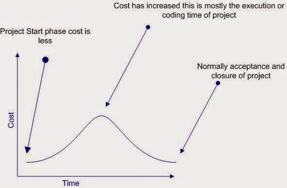
Below is a sample figure which shows all the documents in relevant phases.


Phase mapping with UML documents

punjabtechnicaluniversity.blogspot.in


Twisted Question: - What is Modeling and why UML ?

As the name suggest UNIFIED MODELING LANGUAGE.Modelling has been around for years, not only in software field but also in other trades like civil, mechanical etc.

Example in civil engineering drawing the main architecture built of diagram is a model by itself.Modelling makes complex and huge system to break up in to simple and discrete pieces that can be individually understood. Example simple flowchart drawing is modeling.

There are two main advantages of modeling:-

1. Readability: - Representing your whole architecture in flowchart, class diagrams, ER diagrams etc makes your project more readable. Especially when programmer’s change jobs handover becomes easier. More the project is not readable more the dependencies.

2. Reusability: - After the system is more readable and broken down to pieces, it becomes easier to identify redundant and similar modules. Thus increasing reusability.

So why UML, well different language’s have different ways of coding and syntaxes. In order to bring all languages in one roof UML is in to picture. As the term comes in UNIFIED, it unifies all disparate languages in one roof so that can be understood by people who are working on some other platforms.

punjabtechnicaluniversity.blogspot.in


Twisted Question :- Explain in short all types of diagrams in UML ?

There are nine types of diagrams in UML :-

1.Use case diagram:
They describe "WHAT" of a system rather than "HOW" the system does it.They are used to identify the primary elements and processes that form the system. The primary elements are termed as "actors" and the processes are called "use cases." Use Case diagrams shows "actors" and there "roles".

2.Class diagram:
From the use case diagram we can now go to detail design of system , for which the primary step is class diagram.The best way to identify classes is to consider all "NOUNS" in use cases as classes , "VERBS" as methods of classes, relation between actors can then be used to define relation between classes.The relationship or association between the classes can be either an "is-a" or "has-a" relationship which can easily be identified from use cases.

3.Object diagram:
An object is an instance of a class.Object diagram captures the state of classes in the system and their relationships or associations at a specific point of time.

4.State diagram:
A state diagram, as the name suggests, represents the different states that objects in the system undergo during their life cycle.Object change in response to certain simulation sothis simulation effect is captured in state diagram.So basically it has a initial state and final state and events that happen in between them.Whenever you think that some simulations are complicated you can go for this diagram.

5.Sequence diagram:
Sequence diagrams can be used to explore the logic of a complex operation, function, or procedure.They are called sequence diagrams because sequential nature is shown via ordering of messages.First message starts at the top and the last message ends at bottom.The important aspect of a sequence diagram is that it is time-ordered. This means that the exact sequence of the interactions between the objects is represented step by step. Different objects in the sequence diagram interact with each other by passing "messages".

6.Collaboration diagram:
A collaboration diagram groups together the interactions between different objects to fulfill a common purpose.

7.Activity diagram:
Activity diagram is typically used for business process modeling, for modeling the logic captured by a single use case , or for visualizing the detailed logic of a business rule.Complicated process flows in the system are captured in the activity diagram.Similar to a state diagram, an activity diagram also consists of activities, actions, transitions, initial and final states, and guard conditions.But difference is state diagrams are in context
of simulation while activity gives detail view of a business logic.

8.Deployment diagram:
Deployment diagrams show the hardware for your system, the software that is installed on that hardware, and the middleware used to connect the disparate machines to one another.It shows how the hardware and software work together to run a system.In one line its shows the deployment view of the system.

9.Component diagram:
The component diagram represents the high-level parts that make up the system.From .NET angle point of view they form the "NAMESPACES".This diagram depicts, at a high level, what components form part of the system and how they are interrelated.Its shows the logical grouping of classes or group of other components.

Note :- The best way to remember all the blocks of UML is ”Serve cool SOUP during church ceremony” that covers State chart,Class diagrams,Sequence diagram,Object diagram,Use Case diagram,Package diagram,Deployment diagram,Collaboration diagram,Component diagram:.

punjabtechnicaluniversity.blogspot.in


The Unified Modeling Language (UML) is a graphical language for visualizing,specifying, constructing, and documenting the artifacts of a software-intensive system.UML provides blue prints for business process, System function,programming language statements,database schemas and reusable components.

punjabtechnicaluniversity.blogspot.in


It is a Form of attack on a database-driven Web site in which the attacker executes unauthorized SQL commands by taking advantage of insecure code on a system connected to the Internet, bypassing the firewall. SQL injection attacks are used to steal information from a database from which the data would normally not be available and/or to gain access to an organization’s host computers through the computer that is hosting the database.

SQL injection attacks typically are easy to avoid by ensuring that a system has strong input validation.

As name suggest we inject SQL which can be relatively dangerous for the database.

Example this is a simple SQL

SELECT email, passwd, login_id, full_name FROM members WHERE email = 'x'

Now somebody does not put “x” as the input but puts “x ; DROP TABLE members;”. So the actual SQL which will execute is :-

SELECT email, passwd, login_id, full_name FROM members WHERE email = 'x' ; DROP TABLE members;

Think what will happen to your database 

punjabtechnicaluniversity.blogspot.in


If a table has multiple AFTER triggers, then you can specify which trigger should be executed first and which trigger should be executed last using the stored procedure sp_settriggerorder. All the other triggers are in an undefined order which you cannot control.

punjabtechnicaluniversity.blogspot.in


There are two types of triggers :-

 INSTEAD OF triggers

INSTEAD OF triggers fire in place of the triggering action. For example, if an INSTEAD OF UPDATE trigger exists on the Sales table and an UPDATE statement is executed against the Salestable, the UPDATE statement will not change a row in the sales table.

Instead, the UPDATE statement causes the INSTEAD OF UPDATE trigger to be executed, which may or may not modify data in the Sales table.

AFTER triggers

AFTER triggers execute following the SQL action, such as an insert, update, or delete.This is the traditional trigger which existed in SQL SERVER.
INSTEAD OF triggers gets executed automatically before the Primary Key and the Foreign Key constraints are checked, whereas the traditional AFTER triggers gets executed after these constraints are checked.

Unlike AFTER triggers, INSTEAD OF triggers can be created on views.

punjabtechnicaluniversity.blogspot.in


BCP (Bulk Copy Program) is a command line utility by which you can import and export large amounts of data in and out of SQL SERVER database.

Below is a sample which shows BCP in action.


Export BCP utility in action


Import BCP utility in action

punjabtechnicaluniversity.blogspot.in


There are three types of replication supported by SQL SERVER:-

Snapshot Replication.

Snapshot Replication takes snapshot of one database and moves it to the other database.After initial load data can be refreshed periodically.The only disadvantage of this type of replication is that all data has to copied each time the table is refreshed.

Transactional Replication

In transactional replication data is copied first time as in snapshot replication , but later only the transactions are synchronized rather than replicating the whole database.You can either specify to run continuously or on periodic basis.

Merge Replication.

Merge replication combines data from multiple sources into a single central database.Again as usual the initial load is like snapshot but later it allows change of data both on subscriber and publisher , later when they come on-line it detects and combines them and updates accordingly.

punjabtechnicaluniversity.blogspot.in


Replication is way of keeping data synchronized in multiple databases. SQL server replication has two important aspects publisher and subscriber.

Publisher
Database server that makes data available for replication is called as Publisher.

Subscriber
Database Servers that get data from the publishers is called as Subscribers.

punjabtechnicaluniversity.blogspot.in


DBCC (Database Consistency Checker Commands) is used to check logical and physical consistency of database structure.DBCC statements can fix and detect problems.They are grouped in to four categories :-

1. Maintenance commands like DBCC DBREINDEX , DBCC DBREPAIR etc , they are mainly used for maintenance tasks in SQL SERVER.

2 Miscellaneous commands like DBCC ROWLOCK , DBCC TRACEOFF etc , they are mainly used for enabling row-level locking or removing DLL from memory.

3. Status Commands like DBCC OPENTRAN , DBCC SHOWCONTIG etc , they are mainly used for checking status of the database.

4. Validation Commands like DBCC CHECKALLOC,DBCC CHECKCATALOG etc , they perform validation operations on database.

Note :- Check MSDN for list of all DBCC commands , its very much possible specially during DBA interviews they can ask in depth individual commands.

Below is a sample screen in which DBCC SHOWCONTIG command is run.DBCC SHOWCONTIG is used to display fragmentation information for the data and indexes of the specified table.In the sample screen “Customer” table is checked for fragmentation information.If you look at the figure “Scan density” is 100 if everything is contigious in this image it is 95.36% which is decent percentage.So such type of useful information can be collected by DBCC command and database performance and maintenance can be
improved.


DBCC SHOWCONTIG command in action.

punjabtechnicaluniversity.blogspot.in


A transaction is a sequence of operations performed as a single logical unit of work. A logical unit of work must exhibit four properties, called the ACID (Atomicity, Consistency, Isolation, and Durability) properties, to qualify as a transaction:

Atomicity

 A transaction must be an atomic unit of work; either all of its data modifications are performed or none of them is performed.

Consistency
 When completed, a transaction must leave all data in a consistent state. In a relational database, all rules must be applied to the transaction's modifications to maintain all data integrity. All internal data structures, such as B-tree indexes or doubly-linked lists, must be correct at the end of the transaction.

Isolation

Modifications made by concurrent transactions must be isolated from the modifications made by any other concurrent transactions. A transaction either sees data in the state it was in before another concurrent
transaction modified it, or it sees the data after the second transaction has completed, but it does not see an intermediate state. This is referred to as serializability because it results in the ability to reload the starting data and replay a series of transactions to end up with the data in the same state it was in after the original transactions were performed.

Durability

After a transaction has completed, its effects are permanently in place in the system. The modifications persist even in the event of a system failure.

punjabtechnicaluniversity.blogspot.in


The RAISERROR statement is used to produce an ad hoc error message or to retrieve a custom message that is stored in the sysmessages table. You can use this statement with the error handling code presented in the previous section to implement custom error messages in your applications. The syntax of the statement is shown here.

RAISERROR ({msg_id |msg_str }{,severity ,state }
[ ,argument [ ,,...n ] ] ))
[ WITH option [ ,,...n ] ]

A description of the components of the statement follows.

msg_id :-The ID for an error message, which is stored in the error column in sysmessages.

msg_str :-A custom message that is not contained in sysmessages.

severity :- The severity level associated with the error. The valid values are 0–25. Severity levels 0–18 can be used by any user, but 19–25 are only available to members of the fixed-server role sysadmin. When levels 19–25 are used, the WITH LOG option is required.state A value that indicates the invocation state of the error. The valid values are 0–127.

This value is not used by SQL Server.
Argument, . . .
One or more variables that are used to customize the message. For example, you could pass the current process ID (@@SPID) so it could be displayed in the message.

WITH option, . . .
The three values that can be used with this optional argument are described here.

LOG - Forces the error to logged in the SQL Server error log and the NT application log.

NOWAIT - Sends the message immediately to the client.

SETERROR - Sets @@ERROR to the unique ID for the message or 50,000.

The number of options available for the statement make it seem complicated, but it is actually easy to use. The following shows how to create an ad hoc message with a severity of 10 and a state of 1.

RAISERROR ('An error occured updating the NonFatal table',10,1)
--Results--

An error occured updating the NonFatal table The statement does not have to be used in conjunction with any other code, but for our purposes it will be used with the error handling code presented earlier. The following

alters the ps_NonFatal_INSERT procedure to use RAISERROR.
USE tempdb
go
ALTER PROCEDURE ps_NonFatal_INSERT
@Column2 int =NULL
AS
DECLARE @ErrorMsgID int
INSERT NonFatal VALUES (@Column2)
SET @ErrorMsgID =@@ERROR
IF @ErrorMsgID <>0
BEGIN
RAISERROR ('An error occured updating the NonFatal table',10,1)
END

When an error-producing call is made to the procedure, the custom message is passed to
the client. The following shows the output generated by Query Analyzer.

punjabtechnicaluniversity.blogspot.in


UNION SQL syntax is used to select information from two tables.But it selects only distinct records from both the table. , while UNION ALL selects all records from both the tables.

Note :- Selected records should have same datatype or else the syntax will not work.


punjabtechnicaluniversity.blogspot.in


You can use Having Clause with the GROUP BY function in a query and WHERE Clause is applied to each row before they are part of the GROUP BY function in a query.

punjabtechnicaluniversity.blogspot.in


1.User-Defined Functions: User-Defined Functions (UDFs) -- one or more Transact-SQL statements can be used to encapsulate code for reuse. Userdefined functions cannot make a permanent changes to the data or modify database tables. UDF can change only local objects for a UDF, such as local cursors or variables.

2. Distributed Partitioned Views: Distributed partitioned views allow you to partition tables horizontally across multiple servers. So, you can scale out one database server to a group of database servers that cooperate to provide the same performance levels as a cluster of database servers. Due to distributed
partitioned views, SQL Server 2000 now on the first place in the tpc-c tests.

3.New Data Types: These include: bigint, an 8-byte integer type; sql_variant, a data type that allows the storage of data of different data types; and the table data type, which allows applications to store results temporarily for later use.

4. INSTEAD OF and AFTER Triggers: There are INSTEAD OF and AFTER Triggers in SQL Server 2000. INSTEAD OF triggers are executed instead of  the INSERT, UPDATE or DELETE triggering action. AFTER triggers are executed after the triggering action.

5. Cascading Referential Integrity Constraints: There are new ON DELETE and ON UPDATE clauses in the REFERENCES clause of the CREATE TABLE and ALTER TABLE statements.The ON DELETE clause controls what actions are taken if you attempt to delete a row to which existing foreign keys
point. The ON UPDATE clause defines the actions that are taken if you attempt to update a candidate key value to which existing foreign keys point.

6. The ON DELETE and ON UPDATE clauses have two options: NO ACTION :-NO ACTION specifies that the deletion/update fail with an error.

7. CASCADE :-CASCADE specifies that all the rows with foreign keys pointing to the deleted/updated row are also deleted/updated.

8. 32 CPU and 64GB Memory Support: SQL Server 2000 Enterprise Edition running under Windows 2000 DataCenter can support up to 32 CPUs and up to 64GB of physical memory (RAM) on a computer.
√ XML Support: SQL Server 2000 can use XML to insert, update, and delete values in the database, and the database engine can return data as Extensible Markup Language (XML) documents

punjabtechnicaluniversity.blogspot.in


There are lots of options available, you have to choose your option depending upon your requirements. Some of the options you have are: BACKUP/RESTORE, detaching and attaching databases, replication, DTS, BCP, logshipping, INSERT...SELECT, SELECT...INTO, creating INSERT scripts to generate data.

punjabtechnicaluniversity.blogspot.in


Lock escalation is the process of converting a lot of low level locks (like row locks, page locks) into higher level locks (like table locks). Every lock is a memory structure too many locks would mean, more memory being occupied by locks. To prevent this from happening, SQL Server escalates the many fine-grain locks to fewer coarse-grain locks.
Lock escalation threshold was definable in SQL Server 6.5, but from SQL Server 7.0 onwards it's dynamically managed by SQL Server.

punjabtechnicaluniversity.blogspot.in


We can give locking hints that help's you override default decisions made by SQL Server. For instance, you can specify the ROWLOCK hint with your UPDATE statement to convince SQL Server to lock each row affected by that data modification. Whether it's prudent to do so is another story; what will happen if your UPDATE affects 95% of rows in the affected table? If the table contains 1000 rows, then SQL Server will have to acquire 950 individual locks, which is likely to cost a lot more in terms of memory than acquiring a single table lock. So think twice before you bombard your code with ROWLOCKS.

punjabtechnicaluniversity.blogspot.in


Depending on the transaction level six types of lock can be acquired on data :-

Intent

The intent lock shows the future intention of SQL Server's lock manager to acquire locks on a specific unit of data for a particular transaction. SQL Server uses intent locks to queue exclusive locks, thereby ensuring that these locks will be placed on the data elements in the order the transactions were initiated. Intent locks come in three flavors: intent shared (IS), intent exclusive (IX), and shared with intent exclusive (SIX).

IS locks indicate that the transaction will read some (but not all) the resources in the table or page by placing shared locks.

IX locks indicate that the transaction will modify some (but not all) resources in the table or page by placing exclusive locks.

SIX locks indicate that the transaction will read all resources, and modify some(but not all) of them. This will be accomplished by placing the shared locks on the resources read and exclusive locks on the rows modified. Only one SIX lock is allowed per resource at one time; therefore, SIX locks prevent other connections from modifying any data in the resource (page or table), although they do allow reading the data in the same resource.

Shared
Shared locks (S) allow transactions to read data with SELECT statements. Other connections are allowed to read the data at the same time; however, no transactions are allowed to modify data until the shared locks are released.

Update
Update locks (U) are acquired just prior to modifying the data. If a transaction modifies a row, then the update lock is escalated to an exclusive lock; otherwise, it is converted to a shared lock. Only one transaction can acquire update locks to a resource at one time.

Using update locks prevents multiple connections from having a shared lock that want to eventually modify a resource using an exclusive lock. Shared locks are compatible with other shared locks, but are not compatible with Update locks.

Exclusive
Exclusive locks (X) completely lock the resource from any type of access including reads. They are issued when data is being modified through INSERT, UPDATE and DELETE statements.

Schema
Schema modification locks (Sch-M) are acquired when data definition language statements, such as CREATE TABLE, CREATE INDEX, ALTER TABLE, and so on are being executed. Schema stability locks (Sch-S) are acquired when store procedures are being compiled.

Bulk Update
Bulk update locks (BU) are used when performing a bulk-copy of data into a table with TABLOCK hint. These locks improve performance while bulk copying data into a table; however, they reduce concurrency by effectively disabling any other connections to read or modify data in the table.

punjabtechnicaluniversity.blogspot.in


Twisted Question :- What are different types of locks in SQL SERVER ?

Transaction Isolation level decides how is one process isolated from other process.Using transaction levels you can implement locking in SQL SERVER.

There are four transaction levels in SQL SERVER :-

READ COMMITTED
The shared lock is held for the duration of the transaction, meaning that no other transactions can change the data at the same time. Other transactions can insert and modify data in the same table, however, as long as it is not locked by the first transaction.

READ UNCOMMITTED

No shared locks and no exclusive locks are honored. This is the least restrictive isolation level resulting in the best concurrency but the least data integrity.

REPEATABLE READ
This setting disallows dirty and non-repeatable reads. However, even though the locks are held on read data, new rows can still be inserted in the table, and will subsequently be read by the transaction.

SERIALIZABLE
This is the most restrictive setting holding shared locks on the range of data. This setting does not allow the insertion of new rows in the range that is locked; therefore, no phantoms are allowed.

Following is the syntax for setting transaction level in SQL SERVER.

SET TRANSACTION ISOLATION LEVEL SERIALIZABLE

punjabtechnicaluniversity.blogspot.in


Following are the problems that occur if you do not implement locking properly in SQL SERVER.

Lost Updates
Lost updates occur if you let two transactions modify the same data at the same time, and the transaction that completes first is lost. You need to watch out for lost updates with the READ UNCOMMITTED isolation level. This isolation level disregards any type of locks, so two simultaneous data modifications are not aware of each other. Suppose that a customer has due of 2000$ to be paid.He pays 1000$ and again buys a product of 500$.Lets say that these two transactions are now been entered from two different counters
of the company.Now both the counter user start making entry at the same time 10:00 AM.Actually speaking at 10:01 AM the customer should have 2000$-1000$+500 = 1500$ pending to be paid.But as said in lost updates the first transaction is not considered and the second transaction overrides it.So the final pending is 2000$+500$ = 2500$.....I hope the company does not loose the customer.

Non-Repeatable Read

Non-repeatable reads occur if a transaction is able to read the same row multiple times and gets a different value each time.Again, this problem is most likely to occur with the READ UNCOMMITTED isolation level. Because you let two transactions modify data at the same time, you can get some unexpected results. For instance, a customer wants to book flight , so the travel agent checks for the flights availability.Travel agent finds a seat and goes ahead to book the seat.While the travel agent is booking the seat , some other travel agent books the seat.When this travel agent goes to update the record , he gets error saying that “Seat is already booked”.In short the travel agent gets different status at different times for the seat.

Dirty Reads

Dirty reads are a special case of non-repeatable read. This happens if you run a report while transactions are modifying the data that you're reporting on. For example there is a customer invoice report which runs on 1:00 AM in afternoon and after that all invoices are sent to the respective customer for payments.Lets say one of the customer has 1000$to be paid.Customer pays 1000$ at 1:00 AM and at the same time report is run.Actually customer has no money pending but is still issued a invoice.

Phantom Reads

Phantom reads occur due to a transaction being able to read a row on the first read, but not being able to modify the same row due to another transaction deleting rows from the same table. Lets say you edit a record in the mean time somebody comes and deletes the record , you then go for updating the record which does not exist....Panic.
Interestingly, the phantom reads can occur even with the default isolation level supported by SQL Server: READ COMMITTED. The only isolation level that doesn't allow phantoms is SERIALIZABLE, which ensures that each transaction is completely isolated from others. In other words, no one can acquire any type of locks on the affected row while it is being modified.

Tuesday, January 27, 2015

punjabtechnicaluniversity.blogspot.in


Following are difference between them :-

1. DELETE TABLE syntax logs the deletes thus making the delete operation slow.TRUNCATE table does not log any information but it logs information about deallocation of data page of the table.So TRUNCATE table is faster as compared to delete table.

2. DELETE table can be rolled back while TRUNCATE can not be.

3. DELETE table can have criteria while TRUNCATE can not.

4. TRUNCATE table can not triggers.

punjabtechnicaluniversity.blogspot.in


Redundant Array of Independent Disks (RAID) is a term used to describe the technique of improving data availability through the use of arrays of disks and various data-striping methodologies. Disk arrays are groups of disk drives that work together to achieve higher data-transfer and I/O rates than those provided by single large drives. An array is a set of multiple disk drives plus a specialized controller (an array controller) that keeps track of how data is distributed across the drives. Data for a particular file is written in segments
to the different drives in the array rather than being written to a single drive.

For speed and reliability, it's better to have more disks. When these disks are arranged in certain patterns and use a specific controller, they are called a Redundant Array of Inexpensive Disks (RAID) set. There are several numbers associated with RAID, but the most common are 1, 5 and 10.

RAID 1 works by duplicating the same writes on two hard drives. Let's assume you have two 20 Gigabyte drives. In RAID 1, data is written at the same time to both drives.

RAID1 is optimized for fast writes.

RAID 5 works by writing parts of data across all drives in the set (it requires at least three drives). If a drive failed, the entire set would be worthless. To combat this problem, one of the drives stores a "parity" bit. Think of a math problem, such as 3 + 7 = 10. You can  think of the drives as storing one of the numbers, and the 10 is the parity part. By removing any one of the numbers, you can get it back by referring to the other two, like this: 3 + X= 10. Of course, losing more than one could be evil. RAID 5 is optimized for reads.
RAID 10 is a bit of a combination of both types. It doesn't store a parity bit, so it's fast, but it duplicates the data on two drives to be safe. You need at least four drives for RAID 10. This type of RAID is probably the best compromise for a database server.

Note :- It's difficult to cover complete aspect of RAID in this book.It's better to take some decent SQL SERVER book for in detail knowledge , but yes from interview aspect you can probably escape with this answer.

punjabtechnicaluniversity.blogspot.in


Twisted Question :- When does plage split occurs ?

The 'fill factor' option specifies how full SQL Server will make each index page. When there is no free space to insert new row on the index page, SQL Server will create new index page and transfer some rows from the previous page to the new one. This operation is called page splits. You can reduce the number of page splits by setting the appropriate fill factor option to reserve free space on each index page. The fill factor is a value from 1 through 100 that specifies the percentage of the index page to be left empty. The default value for fill factor is 0. It is treated similarly to a fill factor value of 100, the difference in that SQL Server leaves some space within the upper level of the index tree for FILLFACTOR = 0. The fill factor percentage is used only at the time the index is created. If the table contains read-only data (or data that very rarely changed), you can set the 'fill factor' option to 100. When the table's data modified very often, you can decrease the fill factor to 70% or whatever you think is best.

punjabtechnicaluniversity.blogspot.in


DTS is used to pull data from various sources into the star schema.

punjabtechnicaluniversity.blogspot.in


Twisted Question :- Can you explain the star schema for OLAP ?

The dimensions and measures are physically represented by a star schema.Dimension tables revolve around fact table. A fact table contains a column for each measure as well as a column for each dimension. Each dimension column has a foreign-key relationship to the related dimension table, and the dimension columns taken together are the key to the fact table.

punjabtechnicaluniversity.blogspot.in


Dimensions are arranged in hierarchical levels, with unique positions within each level. For example, a time dimension may have four levels, such as Year, Quarter, Month, and Day. Or the dimension might have only three levels, for example, Year, Week, and Day.

The values within the levels are called members. For example, the years 2002 and 2003 are members of the level Year in the Time dimension

punjabtechnicaluniversity.blogspot.in


Dimensions are the categories of data analysis.For example, in a revenue report by month by sales region, the two dimensions needed are time and sales region.Typical dimensions include product, time, and region.

punjabtechnicaluniversity.blogspot.in


Measures are the key performance indicators that you want to evaluate. To determine which of the numbers in the data might be measures, a rule of thumb is: If a number makes sense when it is aggregated, then it is a measure.

punjabtechnicaluniversity.blogspot.in


OLAP is useful because it provides fast and interactive access to aggregated data and the  ability to drill down to detail.

punjabtechnicaluniversity.blogspot.in


Following are tips which will increase your SQl performance :-

1. Every index increases the time in takes to perform INSERTS, UPDATES and DELETES, so the number of indexes should not be very much. Try to use maximum 4-5 indexes on one table, not more. If you have read-only table, then the number of indexes may be increased.

2. Keep your indexes as narrow as possible. This reduces the size of the index and reduces the number of reads required to read the index.

3. Try to create indexes on columns that have integer values rather than character values.

4. If you create a composite (multi-column) index, the order of the columns in the key are very important. Try to order the columns in the key as to enhance selectivity, with the most selective columns to the leftmost of the key.

5. If you want to join several tables, try to create surrogate integer keys for this purpose and create indexes on their columns.Create surrogate integer primary key (identity for example) if your table will  not have many insert operations.

4. Clustered indexes are more preferable than nonclustered, if you need to select by a range of values or you need to sort results set with GROUP BY or ORDER BY.

5. If your application will be performing the same query over and over on the same table, consider creating a covering index on the table.

6. You can use the SQL Server Profiler Create Trace Wizard with "Identify Scans of Large Tables" trace to determine which tables in your database may need indexes. This trace will show which tables are being scanned by queries instead of using an index.

punjabtechnicaluniversity.blogspot.in

 A clustered index is a special type of index that reorders the way records in the table are physically stored. Therefore table can have only one clustered index. The leaf nodes of a clustered index contain the data pages.

A nonclustered index is a special type of index in which the logical order of the index does not match the physical stored order of the rows on disk. The leaf node of a nonclustered index does not consist of the data pages. Instead, the leaf nodes contain index rows.


punjabtechnicaluniversity.blogspot.in


Indexes in SQL Server are similar to the indexes in books. They help SQL Server retrieve the data quicker.

There are clustered and nonclustered indexes.


punjabtechnicaluniversity.blogspot.in


INNER JOIN

Inner join shows matches only when they exist in both tables.Example in the below SQL there are two tables Customers and Orders and the inner join in made on Customers Customerid and Orders Customerid.So this SQL will only give you result with customers who have orders.If the customer does not have order it will not display that record.

SELECT Customers.*, Orders.* FROM Customers INNER JOIN Orders ON Customers.CustomerID =Orders.CustomerID 

LEFT OUTER JOIN

Left join will display all records in left table of the SQL statement.In SQL below customers with or without orders will be displayed. Order data for customers without orders appears as NULL values. For example, you want to determine the amount ordered by each customer and you need to see who has not ordered anything as well. You can also see the LEFT OUTER JOIN as a mirror image of the RIGHT OUTER JOIN (Is covered in the next section) if you switch the side of each table.

SELECT Customers.*, Orders.* FROM Customers LEFT OUTER JOIN Orders ON Customers.CustomerID =Orders.CustomerID

RIGHT OUTER JOIN

Right join will display all records in right table of the SQL statement.In SQL below all orders with or without matching customer records will be displayed. Customer data for orders without customers appears as NULL values. For example, you want to determine if there are any orders in the data with undefined CustomerID values (say, after a conversion or something like it). You can also see the RIGHT OUTER JOIN as a mirror image of the LEFT OUTER JOIN if you switch the side of each table.

SELECT Customers.*, Orders.* FROM Customers RIGHT OUTER JOIN Orders
ON Customers.CustomerID =Orders.CustomerID

Popular

Archive

North India Campus. Powered by Blogger.

Welcome to North India Campus

Search Question Paper

Labels

1st & 2nd Semester BE 1st Semester B.Com 1st Semester BBA 1st Semester BCA (D) 1st Semester Bsc. IT (D) 1st Semester Bsc. IT 1 1ST Semester M.SC IT(D) 1st Semester M.Tech 1ST Semester MBA 1st Semester MCA 1st Semester MCA (D) 2nd Sem B.Com 2nd Sem BB 2nd Sem BBA 2nd Sem BCA 2nd Sem BCA (D) 2nd Sem BSC IT(D) 2nd Sem BSC(IT) 2nd Semester MBA A Foundation Course in Human Values and Professional Ethics Accounting and Financial Management Accounting and Financial Managementm ACCOUNTING FOR MANAGEMENT Adolescence and Family Education B.Ed (2012) Adolescence And Family Education B.Ed (Dec 2013) Adolescence And Family Education B.Ed (Dec 2014) ADVANCE SOFTWARE ENGINEERING Advanced Accounting 2 ADVANCED COMMUNICATION SYSTEMS ADVANCED MATHEMATICS FOR ENGINEERS Aligarh Muslim University Applied Physics 1 B.Ed (Dec 2008) B.Ed (Dec 2009) B.Ed (Dec 2011) B.Ed (Dec 2012) B.Ed (Dec 2013) B.Ed (Dec 2014) B.Ed (June 2008) B.Ed (June 2009) B.Ed (June 2015) BA 1 Syllabus Bachelor in Science Fashion and Technology Basic Accounting Basic Chemistry Basic Electrical Engineering Basic Electronics Basic Mathematics BSC 1 Basoc Accounting BBA 1 BBA 2 BCA Question Papers BCA Syllabus 1 Bridge Course in Mathematics Bsc.IT Business Communication-1 Business Communication-2 Business Communication-I 2 Business Environment 2 Business Laws 1 Business Mathematics Business Organisation and Management Business Statistics 2 C C Programming C Programming Bsc IT 1 C Programming Lecture Videos CADM 1st Semester Communication 2 Communication and Soft Skills Communication Skills Communication Skills 1 Communicative English Computer and Education B.Ed (Dec 2011) Computer and Education B.Ed (Dec 2012) Computer Applications Computer Fundamental Computer Graphics Video Lecture Computer in Education B.Ed (Dec 2008) Computer in Education B.Ed (Dec 2009) Computer In Education B.Ed (Dec 2013) Computer in Education B.Ed (Dec 2014) Computer Mathematical Foundation MCA D Computer Networks 1st Semester Computer Operating System Computer Organization and Assembly Language Computer System Architecture 2 Corporate Accounting Curriculum and Instruction B.Ed (Dec 2009) Curriculum and Instruction B.Ed (Dec 2011) Curriculum and Instruction B.Ed (Dec 2012) Curriculum and Instruction B.Ed (Dec 2013) Curriculum and Instruction B.Ed (Dec 2014) Curriculuman and Instruction B.Ed (Dec 2008) DATA COMMUNICATION NETWORK Data Structure 2 Data Structures 2 data structures 2 BCA D Data Structures Through C 2 Database Management with Microsoft Access Bsc IT 1 Delhi University News Desktop Publishing Tools 2 Digital Circuits and Logic Design 2 Digital Circuits and Logic Design 2 BCA D Digital Electronics 2 Digital Electronics Fundamentals 2 Distance Education B.Ed (Dec 2008) Distance Education B.Ed (Dec 2009) Distance Education B.Ed (Dec 2011) Distance Education B.Ed (Dec 2012) Distance Education B.Ed (Dec 2013) Distance Education B.Ed (Dec 2014) Dot Net Interview Questions & Answers. Education and Evaluation B.Ed (Dec 2009) Education and Society B.Ed (Dec 2008) Education and Society B.Ed (Dec 2009) Education and Society B.Ed (Dec 2011) Education and Society B.Ed (Dec 2012) Education and Society B.Ed (Dec 2013) Education and Society B.Ed (Dec 2014) Education Technology B.Ed (Dec 2009) Educational Evaluation B.Ed (Dec 2008) Educational Evaluation B.Ed (Dec 2011) Educational Evaluation B.Ed (Dec 2012) Educational Evaluation B.Ed (Dec 2013) Educational Evaluation B.Ed (Dec 2014) Educational Technology B.Ed (Dec 2008) Educational Technology B.Ed (Dec 2011) Educational Technology B.Ed (Dec 2012) Educational Technology B.Ed (Dec 2013) ELECTRONICS SYSTEM DESIGN Engineering Drawing and Graphics Engineering Mathematics Engineering Question Paper set 1 Engineering Syllabus English and Communication Skills English and Communication Skills 2 Environmental Science 2 Finaicial Accounting Financial Accounting Financial Management 2 Sem Fundamentals of Information Technology Bsc 1 Guidance and Counseling B.Ed (Dec 2008) Guidance and counseling B.Ed (Dec 2009) Guidance and Counseling B.Ed (Dec 2011) Guidance and Counseling B.Ed (Dec 2012) Guidance and Counseling B.Ed (Dec 2013) HIV and Aids Education B.Ed (Dec 2011) HIV and Aids Education B.Ed (Dec 2012) HIV and Aids Education B.Ed (Dec 2013) Hotel Management and Air Lines Syllabus HP University News Human Resource Management Human Resource Management 2 Information Management Information Technology for Management Intoduction to microprocessor 2 BCA D Introduction of Computers BBA1 Introduction to Computers 2 Introduction to I.T MCA D Introduction to Information Technology Introduction to Information Technology(BCA) Kurukshetra University News Lecture 20 Clipping -- Lines And Polygons Macro Economics 2 Management Syllabus Managerial Economics Marketing Management 2 Master Of Technology M-Tech Syllabus MBA Papers MCA Notes MCA Question Papers Mercantile Law 2 Metal Cutting Question Paper Metal Forming Question Paper Micro Economics Network Security NEURAL NETWORKS & FUZZY LOGIC Object Oriented Programming in C++ Object Oriented Programming in Cpp OOP CPP 2 Operating system (BCA) Operating System Bsc IT 1 Organisational Behaviour Organization Behaviour 2 Other Universities Others Panjab University News PCM 2 BCA D PGDCA Pharmacy Syllabus Principles and Practices of Management principles of management 2 Production and Operations Management 2 Programming in C Programming in C MCA D Programming Logic Development with C Psychology of Learning and Development B.Ed (Dec 2013) Psychology of Learning and Development B.Ed (Dec 2008) Psychology of Learning and Development B.Ed (Dec 2009) Psychology of Learning and Development B.Ed (Dec 2011) Psychology of Learning and Development B.Ed (Dec 2012) PTU Affiliated Colleges of Integerated College PTU Affiliated Colleges of Management College PTU Affiliated Colleges of Architecture PTU Affiliated Colleges of Engineering PTU Affiliated Colleges of Pharmacy College PTU Forms Download PTU News and Events Quantitative Techniques RDBMS 2 RDBMS-I 2 Relational Database Management System Research Methodology 2 SAD 2 BCA D Syllabus of Computer Applications Syllabus of Journalism and Mass Communication Syllabus of Medical Laboratory Science System Analysis and Design System Analysis and Design 2 System Analysis and Design MCA D Teacher and School B.Ed (Dec 2008) Teacher and School B.Ed (Dec 2009) Teacher and School B.Ed (Dec 2011) Teacher and School B.Ed (Dec 2012) Teacher and School B.Ed (Dec 2013) Teacher of English B.Ed (Dec 2009) Teaching of English B.Ed (Dec 2008) Teaching of English B.Ed (Dec 2011) Teaching of English B.Ed (Dec 2012) Teaching of English B.Ed (Dec 2013) Teaching of Mathematics B.Ed (Dec 2009) Teaching of Mathematics B.Ed (Dec 2011) Teaching of Mathematics B.Ed (Dec 2012) Teaching of Mathematics B.Ed (Dec 2013) Teaching of Science B.Ed (Dec 2008) Teaching of Science B.Ed (Dec 2009) Teaching of Science B.Ed (Dec 2011) Teaching of Science B.Ed (Dec 2012) Teaching of Science B.Ed (Dec 2013) Teaching of Social Studies B.Ed (Dec 2008) Teaching of Social Studies B.Ed (Dec 2011) Teaching of Social Studies B.Ed (Dec 2012) Teaching of Social Studiess B.Ed (Dec 2013) Teaching of Social Study B.Ed (Dec 2009) Technical Communication UGC NET Computer Science Question Paper Uttarakhand Open University Video Lecture Web Technologies 1st Semester Web Technologies 2 Welding Technology Question Paper Workshop on IT and E-Commerce 2